Model T200UP with NumaView™ Software
Trace-level, Photolytic, True NO2/NO/NOx Analyzer
Trace-level, Photolytic, True NO2/NO/NOx Analyzer
The Model T200UP provides trace level measurements of NO and NO2 using our Model T200U NOx analyzer combined with a patented high efficiency photolytic converter. Even low temperature molybdenum converters transform other nitrogen-containing compounds such as HNO3, PAN, etc. to a considerable extent. Simultaneous measurements of NO2 performed with molybdenum and photolytic converters have shown significantly different results in the presence of such compounds.
In the photolytic process the sample gas passes through a cell where it is exposed to light at a specific wavelength from an LED array. This causes the NO2 to be selectively converted to NO with negligible interference from other gases. Combined with the proven Model T200U, it provides ultra-sensitive performance, with a lower detectable limit of 0.05 ppb or better, and is ideally suited for NCore research sites and the low-level direct NO2 measurements required for roadside monitoring. Advances in the photolytic converter technology now yields NO2 conversion efficiency that is similar to molybdenum under typical ambient NO2 concentrations, but without the same interferences.
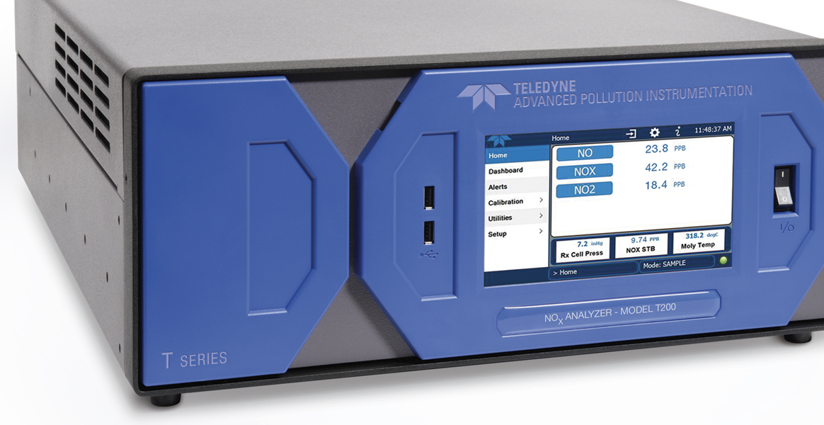
All T Series instruments offer an advanced color display, capacitive touch screen, intuitive user interface, flexible I/0, and built-in data acquisition capability. All instrument set up, control and access to stored data and diagnostic information is available through the front panel, or via RS232, Ethernet, or USB com ports, either locally or by remote connection.
The Model T200UP comes with NumaView™ Software. NumaView™ Remote PC Software allows for a remote connection with virtual interface and data downloading capability to analyzers operating NumaView™ Software.
- Ranges: 0-5 ppb to 0-2,000 ppb, user selectable
- High efficiency photolytic converter with specific conversion of NO2
- Ethernet, RS-232, and (optional) USB com ports
- Front panel USB connections for peripheral devices and firmware upgrades
- 8 analog inputs (optional)
- 50 ppt lower detectable limit
- Catalytic ozone scrubber
- Comprehensive internal data logging with programmable averaging periods
- Ability to log virtually any operating parameter
- Two-year warranty
| Ranges | Min: 0 – 5 ppb full scale Max: 0 – 2,000 ppb full scale (selectable, dual-range supported) |
| Measurement Units | ppb, μg/m3 (selectable) |
| Zero Noise | < 25 ppt (RMS) |
| Span Noise | < 0.5% of reading (RMS) above 5 ppb |
| Lower Detectable Limit | < 50 ppt |
| Zero Drift | < 0.1 ppb/24 hours |
| Span Drift | < 0.5% of reading/24 hours |
| Response Time | < 70 seconds to 95% |
| Linearity | 1% of full scale |
| Precision | 0.5% of reading above 5 ppb |
| Sample Flow Rate | 1,100 cc/min ±10% |
| Power Requirements | 100V-120V, 220V-240V, 50/60 Hz, Typical power 165W |
| Analog Output Ranges | 10V, 5V, 1V, 0.1V (selectable) |
| Recorder Offset | ±10% |
| Included I/O | 1 x Ethernet: 10/100Base-T 2 x RS232 (300-115,200 baud) 2 x USB device ports 8 x opto-isolated digital outputs 6 x opto-isolated digital inputs 4 x analog outputs |
| Optional I/O | 1 x USB com port 1 x RS485 4 x digital alarm outputs Multidrop RS232 2 x 4 – 20mA current outputs |
| Operating Temperature Range | 5 – 40ºC |
| Dimensions (HxWxD) | 7” x 17” x 23.5” (178 x 432 x 597 mm) |
| Weight | Analyzer: 40 lbs (18 kg) External pump: 22 lbs (10 kg) |
| Certifications | US EPA: EQNA-0512-200 |
The following table provides a list of items that need regular maintenance to ensure your product remains in good working condition.
| ITEM | ACTION | FREQUENCY | CAL CHECK | MANUAL SECTION |
| 1Particulate filter | Change particle filter | Weekly | No | 10.3.1 |
| Verify test functions | Review and evaluate | Weekly | No | 10.2; Appendix C |
| Zero/span check | Evaluate offset and slope | Weekly | — | 9.3, 9.6, 9.9 |
| 1Zero/span calibration | Zero and span calibration | Every 3 months | — | 9.2, 9.4, 9.5, 9.7, 9.8 |
| 1External zero air scrubber (optional) | Exchange chemical | Every 3 months | No | 10.3.3 |
| 1Perform flow check | Check Flow | Every 6 Months | No | 10.3.7 |
| Internal IZS Permeation Tube | Replace | Annually | Yes | 10.3.2 |
| Perform pneumatic leak check | Verify Leak Tight | Annually or after repairs involving pneumatics | Yes | 10.3.6 |
| 2Pump diaphragm | Replace | Annually | Yes | Refer to diaphragm kit instructions |
| Calibrate UV Lamp Output | Perform lAMP CAL | Prior to zero/span calibration or PMT hardware calibration | — | 5.9.6 & 11.7.2.5 |
| 3PMT sensor hardware calibration | Low-level hardware calibration | On PMT/ preamp changes if | Yes | 11.7.2.8 |
| 0.7 < slope or | ||||
| slope >1.3 | ||||
| 1Sample chamber optics | Clean chamber, windows and filters | As necessary | Yes | 11.7.2.2 & 11.7.2.3 |
| 1Critical flow orifice & sintered filters | Replace | As necessary | Yes | 10.3.4 |
1 These Items are required to maintain full warranty; all other items are strongly recommended.
2 A pump rebuild kit is available from Teledyne API’s Technical Support, including all instructions and required parts.
3 Replace desiccant bags each time the inspection plate for the sensor assembly is removed.