INCA3000
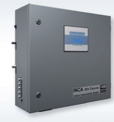

Use with dry gases and indoor locations. With or without sample stream switching
INCA is a modular designed analyzer system for multicomponent gas analysis with key application areas in the Biogas and Natural Gas industries. Objective of the INCA concept is to configure complete analyzer systems from standardized assembly groups for sampling, sample preparation, sensorics, control and data handling in order to meet and solve particular application tasks as efficient as possible. This concept combines best possible analysis results with, at the same time, favorable cost situation for users and supplier. A device configuration tool is available to select and specify all details.
INCA3000 (3XXX resp.) is an analyzer series
• to analyze condensate free gases (without gas cooler)
• for indoor installation (IP 43, 5 to +45° C)
• with or without sample line switching.
Complete detector units
The component-selective INCA detectors are complete detecting units. They comprehend light source (in case of optical methods), measuring chamber, filter and a sensitive (detecting) element such as • NDIR cell for CH4, CO2, C2+,
• Electrochemical cell (EC) for O2, H2S and H2,
• Paramagnetical cell for O2 and
• Acoustic cell for specific gravity.
Complete sensor modules
INCA sensors are complete modules which are classified by „T-numbers“. They comprehend one or severaldetectors as well as electronics and memory storage for e.g. calibration data. Sensor modules can be preconfigured and pre-calibrated ready for use for particular applications such as Biogas (T100), Low Gas (T087) or Natural Gas (T301). Integrating them into an INCA analyzer only requires, apart from the mechanical assembly, to connect the module via a plug to the control system using the internal device bus.
Calibration data on the sensor module
INCA sensors are always calibrated prior to delivery with the resulting data beeing saved as calibration curve directly on the sensor module storage. By using numerous measuring points spread over the measuring range, these calibration data is very precisely assigned which facilitates subsequent calibrations by the user. For this, INCA offers simple and costefficient post calibration routines with just ambient air using zero point for CH4 , C2 +, H2S and H2 and span for O2.
As a particular performance characteristic INCA analyzers provide four different modes of operation:
• Continuous online operation
when determining CH4, CO2. C2+ and O2.
• Quasi-continuous (cycled) operation
Online operation as mentioned above, but with a cycled measurement of approximately 15 minutes with an air purging course of the sensor in between to recondition them. This mode is used to determine H2S and H2 with electrochemical sensors or in general to preserve the working life of moving parts like pumps. For particularly critical measurements (H2S) the patented μPulse procedure is used which further increases operating time, measuring range and measuring accuracy of the electrochemical sensors.
• Operation with sample gas switching
Sequential switching of the measuring system to different sample gas lines from e.g. from different fermenters in biogas plants or in alarm warning devices.
• Quasi-continuous operation
Measurement of several sample gas flows like above, but with a “preferred” process gas stream. A changeover to other streams can be activated externally (e.g. via Profibus) but only if irregularities in the process stream are recognized and need to be verified as well as for control purposes.
The control system is based on an embedded real time operating system. For communication, all components are connected to an internal device bus (Master- Slave principle, fig. 2) which also controls the power supply. The fan control ensures that the analysis system is only supplied with power if the fan is running. The bus concept also reduces the effort for replacement or installation of modules to only a plugin bus connection to be established.
Interfacing options are
USB, RS-232, Ethernet (TCP/IP), Profibus, Profinet, Modbus-TCP and Modbus-RTU.
The Windows-based Software INCACtrl runs on an external computer and allows for
• setting calibration, purge and measurement cycles, conducting fault analyses,
• parameterisation of analogue outputs,
• reading and display of all measurement data and
• remote access for maintenance purposes.
| INCA3000 Technical data | |
| Weight [kg] | 21 |
| Dimensions (WxHxD) [cm] | 68x65x25 |
| Degree of protection | IP43 |
| Setup site | inside |
| Operating temperature | 5° – 45° C |
| Sample gas cooler | x |
| Condensate pump | x |
| Inlets of process gas | 1 – 4 (6) depending on version |
| Inlets of calibration gas | 1 – 2 depending on version |
| Inlets purging gas (air) | 1 |
| Flame barrier | Ex G IIC |
| Power supply | 100 – 240 VAC, 50/60 Hz |
| Max. power consumption | 100 VA |
| Storage temperature | -20° – 60° C |
| CSA approval (optional) | x |
| Ex approval | x |
| INCA3000 Measurement components1) | |||
| Gas component and measuring range |
Measuring accuracy and principle |
||
| CH4 | 0 – 100 Vol. % | ± 1% FS 2) (± 1 Vol.-%) | NDIR |
| CH4 | 0 – 5 Vol.% | ± 3% FS (± 0,15 Vol.-%) | NDIR |
| CH4 | 0 – 1 Vol. % | ± 5% FS (± 0,05 Vol.-%) | NDIR |
| CO2 | 0 – 100 Vol. % | ± 1% FS (± 1 Vol.-%) | NDIR |
| CO2 | 0 – 10 Vol. % | ± 1,5% FS (± 0,15 Vol.-%) | NDIR |
| C2+ | 0 – 20 Vol. % | ± 2,5% FS (± 0,50 Vol.-%) | NDIR |
| H2S | 0 – 50 000 ppm (μPulse) |
≤500 ppm: ±30 ppm >500 ppm: ±15% v. MW 3) |
EC |
| H2S | 0 – 10 000 ppm (μPulse) |
≤ 25 ppm: ± 3 ppm > 25 ppm: ± 15% v. MW |
EC |
| H2S | 0 – 10 000 ppm | ± 3% FS | EC |
| H2S | 0 – 2000 ppm | ≤1000 ppm: ±30 ppm >1000 ppm: ±3% v. MW |
EC |
| H2S | 0 – 100 ppm | ± 3 ppm | EC |
| H2S | 0 – 50 ppm | ± 1,5 ppm | EC |
| H2 | 0 – 4000 ppm | ± 5% FS | EC |
| O2 | 0 – 25 Vol. % | ±0,1 Vol% at zero point ±0,1 Vol% per 10°C ±3% v. MW |
EC Paramagn. |
| Relative density |
0,2 – 2,2 | ± 1% FS | acustic |
| Relative density |
0,5 – 0,8 | ± 3% FS | calculated 4) |
| Heating value |
8-11,5 KWh/m3 | ± 1,5% FS | calculated 4) |
| Wobbe index |
10-14,3 KWh/m3 | ± 2% FS | calculated 4) |
1) others upon request
2) “FS”: (Full Scale) – of measuring range end value
3) “v. MW”: of measured value
4) from earlier measured gas components